
MIP/MPR view mode
The MIP/MPR (maximum-intensity projection/multiplanar reconstruction) view allows you to see and interact with cross sections of 2D images.
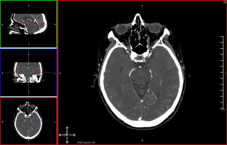
A MIP/MPR image has three orthogonal views. For easy identification in the interface, each view is framed in a color-coded border:
- Green - sagittal
- Blue - coronal
- Red - axial
For colorblind users, the three orthogonal strip views are framed in green (top), blue (mid), and red (bottom).
Each of the colored positional lines in the orthogonal strip views represents the plane of one of the other views. For example, the red positional lines in the top and middle strip views represent the position of the bottom strip view with the corresponding red border.
To assign an orthogonal view as the main view
- Double-click the desired strip view.
All of the methods of navigating the data described in General navigation apply. In addition, you can perform the mode-specific interactions described below.
Changing the image orientation
Orientation information is always visible to clearly indicate how a patient is oriented (posterior, anterior, superior, inferior, right lateral or left lateral).
The letters displayed as orientation labels at the edge of the image come from the DICOM source data, and could vary depending on the data set (if the data was generated in a different language, for example).
In MIP/MPR view mode, patient orientation is indicated using an interactive orientation widget in the bottom right of the image. You can snap the volume to any of the six standard orientations by clicking the spheres on the orientation axis.

Scrolling through images
You can scroll using either the Scroll tool or, when a tool other than Scroll is selected, you can scroll using mouse and keyboard or touch gestures.
To scroll using the Scroll tool
- Click the Scroll (
 ) tool.
 - Click the main view, then drag up or down.
To scroll using mouse and keyboard
Do one of the following:
- Scroll up and down with the mouse wheel.
- Press the Right arrow key to advance to the next slice and press the Left arrow key to go back to the previous slice.
To scroll using touch gestures
- Drag up/down.
Alternately, to scroll through single images:
- Tap near the top or bottom of the view
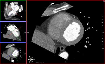
Manipulating planes
The following procedures describe how to manipulate the planes in the strip views.
To move a plane orthogonally
- Click a solid part of a positional line and drag.
To rotate a plane
- Click a dashed part of a positional line and drag.
To freely move a set of positional lines
- Click in the center of the “cross hair” formed by the positional lines and drag.
You can also instantly center the positional lines on a region of interest by directly triangulating a point.
To directly triangulate a point
- Hold CTRL and click on a desired point in any of the strip views. (Hold CMD and click on Mac)
The following double oblique view was created using these methods.
Using curved MPR
You can assign the curved MPR view to the main view by double-clicking the curved MPR view, as seen in the following example.
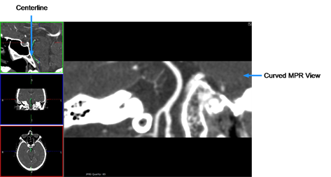
The following procedures describe how to use the curved MPR view.
To enable curved MPR
- Select CMPR from the view menu.
By default, the bottom left pane becomes the curved MPR.
To define a centerline
Do one of the following:
- Hold down the left mouse button and draw the centerline in any of the views. (desktop only)
- Draw the centerline by dragging your finger on any of the views. (touchscreen only)
- Define a centerline by clicking points in any of the views.
You can zoom and scroll through slices while defining a centerline.
To adjust the centerline
- Click and drag any of the handles along the centerline.
To rotate the curved MPR view
- Click and drag anywhere in the curved MPR view.
To reset curved MPR (desktop only)
- Press the D key.
To undo changes to the centerline (desktop only)
- Press the Z key.
Pressing the Z key repeatedly will undo successive changes.
Working with thick slabs
Thick slabbing is useful for viewing a thicker portion of the data in a single image.
In some implementations, thick slabbing will be enabled by default as soon as you select the MIP/MPR view mode.
To enable thick slab
- Select Thick Slab
 from the view menu. The thickness of the slab will be displayed in the view (by default, this is 10 times the acquisition slice thickness).
To adjust the thickness of the slab
- Click the + or - buttons.